Difference between revisions of "USRP: Menyambungkan ClockTamer ke USRP1"
Onnowpurbo (talk | contribs) |
Onnowpurbo (talk | contribs) |
||
| Line 44: | Line 44: | ||
==RFX900/RFX1800 16-pin connector== | ==RFX900/RFX1800 16-pin connector== | ||
| − | + | Jika kita mempunyai RFX daughter board yang baru kemungkinan besar tidak punyai connector 16-pin J24 yang di solder. Kita akan menginginkan untuk menyolder connector yang di berikan J24 untuk memastikan ClockTamer tersambung di USRP1. Ini memang tidak menjadi keharusan karena ClockTamer akan bekerja dengan baik tanpa connector ini. | |
| − | J24 | + | Connector J24 juga dapat digunakan untuk berkomunikasi dengan ClockTamer tywithout a miniUSB cable, but this feature is in beta stage and is not recommended for new users. |
Fan connector's current limiting resistor | Fan connector's current limiting resistor | ||
| Line 53: | Line 53: | ||
[[Image:Current-limiting-resistor.jpg|center|200px|thumb]] | [[Image:Current-limiting-resistor.jpg|center|200px|thumb]] | ||
| − | |||
| − | |||
==ClockTamer installation== | ==ClockTamer installation== | ||
Revision as of 19:09, 2 March 2012
Tulisan ini akan fokus pada cara menyambungkan ClockTamer ke USRP1. Sebetulnya ClockTamer dapat digunakan untuk USRP 2, N2x0, E1x0 dan B1x0. Secara umum, untuk menggunakan ClockTamer dengan USRP selain USRP1 kita perlu menyambungkannya ke "input 10MHz external reference" dan mengkonfigurasi ClockTamer agar membangkitkan frekuensi 10MHz.
USRP1
Instalasi ClockTamer ke USRP1 terdiri dari tiga (3) tahapan:
- Modifikasi USRP1 untuk men-disable internal USRP1 clock reference dan enable external clock input.
- Terminasi yang baik USRP1 clock input.
- (optional) instalasi 16-pin connector di RFX daughter board.
- (optional) hilangkan R7 current limiting resistor.
- Instalasi ClockTamer di USRP1.
Langkah ini akan di jelaskan dengan lebih detail di bawah ini.
Modifikasi USRP1
Berdasarkan USRP wiki, kita perlu mengikuti urutan langkah berikut untuk menyambungkan external clock ke USRP:
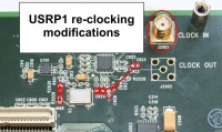
- Solder SMA connector ke J2001. Ini adalah clock input. Hati-hati waktu menyolder jangan sampai merusak sambungan antara J2001 to C927.
- Perlu dicatat bahwa kita tidak bisa memasukan TVRX di RXB jika kita sudah melakukan hal ini.
- Pindahkan R2029 ke R2030. Ini akan men-disable onboard clock. R2029/R2030 adalah 0-ohm resistor. Langkah ini sebetulnya tidak fatal.
- Pindahkan C925 ke C926.
- Buang C924.
Terminasi clock input dengan resistor 50 Ohm
Sangat di sarankan untuk memasang resistor terminasi 50 Ohm di sisi USRP apakah anda akan menggunakan output ClockTamer CMOS atau half-LVDS.
Jika kita menggunakan CMOS output dari ClockTamer maka kemungkinan besar akan jalan tanpa terminating resistor, sejauh ini belum ada laporan kerusakan USRP karena ketiadaan terminating resistor, tapi cara ini sangat diluar spec. Tapi jangan complain kalau USRP anda terbakar karena mengunakan ClockTamer tanpa terminating resistor di USRP1.
Jika kita merencanakan menggunakan output half-LVDS dari ClockTamer, maka terminating resistor wajib digunakan agar dia beroperasi dengan baik. Menggunakan output half-LVDS tanpa terminating resistor di J2001 akan menyebabkan sinyal membalik dan USRP1 tidak mungkin mengunci ke clock,
Catatan: kita harus menyolder terminating resistor di USRP dekat connector input clock J2001. Jika kita menyolder 50 Ohm resistor di ClockTamer bukan di USRP, dia tidak akan bekerja.
"50 Ohm resistor" adalah istilah yang biasa digunakan di diskusi RF yang biasanya berarti resistor yang mempunyai nilai dekat dengan 50 ohm. Baik 49.9 Ohm atau 51 Ohm resistor adalah OK. Kami biasanya menggunakan 51 Ohm resistor.
Dibawah adalah gambar cara menyolder terminating resistor ke J2001. Jika anda mengetahui cara yang lebih baik / lebih aman - mohon kami diberitahu (dan kirimkan gambarnya kalau bisa).
RFX900/RFX1800 16-pin connector
Jika kita mempunyai RFX daughter board yang baru kemungkinan besar tidak punyai connector 16-pin J24 yang di solder. Kita akan menginginkan untuk menyolder connector yang di berikan J24 untuk memastikan ClockTamer tersambung di USRP1. Ini memang tidak menjadi keharusan karena ClockTamer akan bekerja dengan baik tanpa connector ini.
Connector J24 juga dapat digunakan untuk berkomunikasi dengan ClockTamer tywithout a miniUSB cable, but this feature is in beta stage and is not recommended for new users. Fan connector's current limiting resistor
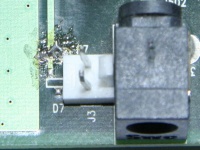
If you want to power your ClockTamer from the USRP1's fan connector, and still be able to power the fan, you have to replace a current limiting resistor R7 with 0 Ohm resistor or a short circuit. This resistor is located right next to the fan power connector J3. Picture below shows the location of the R7 resistor with a short circuit instead of the actual resistor. Soldering on the picture is quite rough, we know you could do better :)
ClockTamer installation
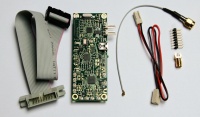
Package contents
ClockTamer package should contain the following items:
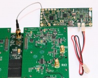
- Flat ribbon cable. It can be used to connect a ClockTamer to RFX daughter board connector if you place ClockTamer remotely. It will not be used in this manual, because the normal way to place ClockTamer is to place it directly on the RFX board connector (see below).
- ClockTamer itself. If your ClockTamer is GPS enabled, it have a female U.FL pigtail attached to it (not shown on the picture below). Female U.FL pigtail is used to connect ClockTamer to GPS antenna.
- Male U.FL pigtail. Used to connect ClockTamer to USRP1 clock input.
- 2-wire power cable.
- 16-pin connector to solder to RFX daughter board.
- SMA connector to solder to USRP1 clock input.
- GPS antenna (only if ClockTamer is GPS-enabled, not shown on the picture below).
Connecting pigtail
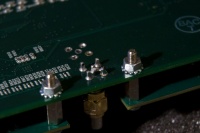
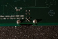
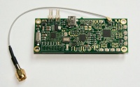
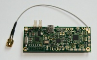
First, connect male U.FL pigtail to the ClockTamer as shown on the pictures below. Only CMOS output #1 is enabled by default, and thus it requires less effort from you to get your setup working. We strongly encourage you to use it. If you want to enable other outputs, you can do this with ClockTamer GUI or manually with ClockTamer control protocol.
Make sure to connect pigtail securely. Loose connection may lead to bad performance or non-responsive USRP1.
Picture of the pigtail connected to output #1 - the default CMOS output.
Picture of the pigtail connected to output #0 - a half-LVDS output. You have to enable this output before using it (see above).
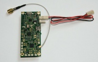
Connecting power cord
Now, connect power cord to the ClockTamer. ClockTamer power connectors are connected directly to each other to allow "chained" connection of the second load (another ClockTamer or a fan). Thus you can connect power cord to any of the power connectors, both will work.
Connecting to a USRP1 clock input
Then connect ClockTamer to the USRP1 clock input, as shown on the picture below. Make sure to tighten the connector securely.
Placing ClockTamer and power connection
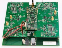
This step is pretty easy. Just place ClockTamer as shown on the picture bellow to fixate it inside of the USRP1 and connect the power cord to the USRP1's fan connector. If you don't have J24 connector, you have to find some other place for your ClockTamer to be fixated. If you do so, make sure to not short-circuit any wires on the ClockTamer or the USRP1.
Connecting the USRP1's fan
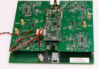
If you have removed the power limiting resistor from the fan power connector (see above), then you can connect the USRP1's fan to the ClockTamer, as shown on the picture.
Testing
- Power on your USRP1.
- If you ClockTamer is NOT connected to miniUSB, it should NOT have its LED lighting. If your ClockTamer IS connected to miniUSB, its LED SHOULD blink once and then light continuously.
- One of USRP1's LEDs should blink fast.
- Use some application from GnuRadio or UHD to check that you can get data from your USRP1 or send data to it as usual. We prefer to use usrp_fft.py for this purpose.
Referensi
- http://shop.fairwaves.ru/clock-tamer
- http://code.google.com/p/clock-tamer/wiki/ClockTamerUSRPInstallation
Pranala Menarik
Persiapan
- USRP: High Precision Clock
- USRP: Menyambungkan ClockTamer ke USRP1
- USRP: Instalasi Board
- OpenBTS: GIT Source Code
OpenBTS 2.6
- GNURadio
- GNURadio: Ubuntu Install
- GNURadio: Spectrum Analizer GSM
- GNURadio: Mengubah board RFX1800 menjadi RFX900
- GNURadio: Programming Untuk Pemula
- OpenBTS: Ubuntu Install
- OpenBTS: Konfigurasi
- OpenBTS: Kalibrasi
- OpenBTS: Konfigurasi Asterisk untuk OpenBTS
- OpenBTS: Menjalankan smqueue
- OpenBTS: Mengoperasikan BTS
- OpenBTS: Tampilan di Nokia saat pakai OpenBTS
- OpenBTS: Operasi 1800 MHz
- OpenBTS: Beberapa Tips
- OpenBTS: USRP2
- OpenBTS: Amplifier
- OpenBTS: SMS
OpenBTS 2.8
- GNURadio: Ubuntu 11.10 Install *NOT RECOMMENED*
- GNURadio: Ubuntu 11.10 instalasi menggunakan Repo NOT RECOMMENDED
- GNURadio: Ubuntu 11.10 Instal GNURadio 3.3.0
- GNURadio: Ubuntu 11.10 Install dari GIT GNURadio
- OpenBTS: Ubuntu 11.10 Install
- OpenBTS: 2.8 dari SVN Install RECOMMENDED
- OpenBTS: 2.8 Instalasi Real Time Asterisk
- OpenBTS: 2.8 Konfigurasi
- OpenBTS: Database SQLite
Ettus E110
- OpenBTS: E110 Cara Login
- OpenBTS: E110 Install Image di MicroSD
- OpenBTS: E110 Cek Daughter Board
- OpenBTS: E110 Mengubah Master Clock
- OpenBTS: E110 Bekerja dengan opkg
- OpenBTS: E110 GNURadio
- OpenBTS: E110 Instalasi OpenBTS
- OpenBTS: E110 Instalasi OpenBTS 2.6 *NOT RECOMMENDED*
Lain Lain
- Membuat Base Station GSM Open Source
- Teknologi Selular
- GSM: Daftar Channel Frekuensi
- Wireless Internet
- OpenBSC
- AirProbe
- Base station subsystem
- GSM
- Asterisk
- Mobile phone
Catatan Legal dan Pendukung
- Siapa Bilang OpenBTS Ilegal?
- OpenBTS: Catatan MNC dan MCC Indonesia
- OpenBTS : Alokasi Frekuensi Operator GSM Indonesia
