USRP: Menyambungkan ClockTamer ke USRP1
Tulisan ini akan fokus pada cara menyambungkan ClockTamer ke USRP1. Sebetulnya ClockTamer dapat digunakan untuk USRP 2, N2x0, E1x0 dan B1x0. Secara umum, untuk menggunakan ClockTamer dengan USRP selain USRP1 kita perlu menyambungkannya ke "input 10MHz external reference" dan mengkonfigurasi ClockTamer agar membangkitkan frekuensi 10MHz.
USRP1
Instalasi ClockTamer ke USRP1 terdiri dari tiga (3) tahapan:
- USRP1 modification to disable internal USRP1 clock reference and enable external clock input.
- Proper termination of the USRP1 clock input.
- 16-pin connector installation on a RFX daughter board (optional).
- R7 current limiting resistor removal (optional).
- ClockTamer installation on a USRP1.
All these steps are described in more details below.
Modifikasi USRP1
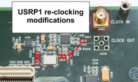
According to Synchronizing multiple USRP1s on USRP wiki, bullet "For the slave boards" you should do following modifications in order to connect external clock to USRP:
   Solder an SMA connector into J2001. This is the clock input. Be careful when soldering the SMA connector so you don't break the delicate trace from J2001 to C927.
   Note that you won't be able to fit a TVRX in the RXB slot anymore once you do this.
   Move R2029 to R2030. This disables the onboard clock. R2029/R2030 is a 0-ohm resistor. This step is not strictly necessary.
   Move C925 to C926.
   Remove C924.
Terminating clock input with 50 Ohm resistor
We strongly encourage you to install 50 Ohm termination resistor on USRP side no matter whether you use ClockTamer's CMOS or half-LVDS output (read below how to do this). If you use a CMOS output of ClockTamer then everything will likely work without terminating resistor and we're not aware of any damaged USRP due to absence of this terminating resistor, but such usage is out of specs. Don't blame us if you burn your USRP by using ClockTamer without installing the terminating resistor on USRP1. If you plan to use a half-LVDS output of ClockTamer, then terminating resistor is a must to get it working. Using half-LVDS output without a proper terminating resistor at J2001 will result in signal bouncing and USRP1 will not be able to lock to the clock.
Note: You must solder termination resistor to USRP near the clock input connector J2001. If you solder 50 Ohm resistor to ClockTamer instead of USRP, it will not work.
"50 Ohm resistor" is a term often used in RF discussions and usually means resistors with a nominal close to 50 Ohm. Both 49.9 Ohm or 51 Ohm resistors are ok. We use 51 Ohm resistors in our setups usually.
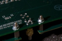
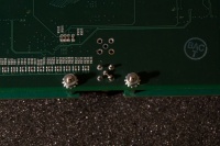
Below are pictures of our way of soldering an terminating resistor to J2001. If you find a better/safer way - please let us know (and send us pictures if possible).
RFX900/RFX1800 16-pin connector
If you have new RFX daughter board most likely it don't have J24 16-pin connector soldered. You may want to solder the provided connector to J24 to securely fixate ClockTamer inside of a USRP1. This is not strictly required and ClockTamer will perfectly work without this connector.
J24 connector may also be used to communicate with ClockTamer without a miniUSB cable, but this feature is in beta stage and is not recommended for new users. Fan connector's current limiting resistor
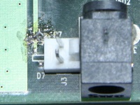
If you want to power your ClockTamer from the USRP1's fan connector, and still be able to power the fan, you have to replace a current limiting resistor R7 with 0 Ohm resistor or a short circuit. This resistor is located right next to the fan power connector J3. Picture below shows the location of the R7 resistor with a short circuit instead of the actual resistor. Soldering on the picture is quite rough, we know you could do better :)
ClockTamer installation Package contents
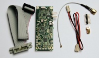
ClockTamer package should contain the following items:
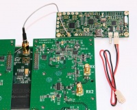
   Flat ribbon cable. It can be used to connect a ClockTamer to RFX daughter board connector if you place ClockTamer remotely. It will not be used in this manual, because the normal way to place ClockTamer is to place it directly on the RFX board connector (see below).
   ClockTamer itself. If your ClockTamer is GPS enabled, it have a female U.FL pigtail attached to it (not shown on the picture below). Female U.FL pigtail is used to connect ClockTamer to GPS antenna.
   Male U.FL pigtail. Used to connect ClockTamer to USRP1 clock input.
   2-wire power cable.
   16-pin connector to solder to RFX daughter board.
   SMA connector to solder to USRP1 clock input.
   GPS antenna (only if ClockTamer is GPS-enabled, not shown on the picture below).
Connecting pigtail
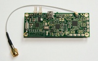
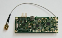
First, connect male U.FL pigtail to the ClockTamer as shown on the pictures below. Only CMOS output #1 is enabled by default, and thus it requires less effort from you to get your setup working. We strongly encourage you to use it. If you want to enable other outputs, you can do this with ClockTamer GUI or manually with ClockTamer control protocol.
Make sure to connect pigtail securely. Loose connection may lead to bad performance or non-responsive USRP1.
Picture of the pigtail connected to output #1 - the default CMOS output.
Picture of the pigtail connected to output #0 - a half-LVDS output. You have to enable this output before using it (see above).
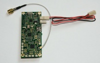
Connecting power cord
Now, connect power cord to the ClockTamer. ClockTamer power connectors are connected directly to each other to allow "chained" connection of the second load (another ClockTamer or a fan). Thus you can connect power cord to any of the power connectors, both will work.
Connecting to a USRP1 clock input
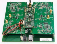
Then connect ClockTamer to the USRP1 clock input, as shown on the picture below. Make sure to tighten the connector securely.
Placing ClockTamer and power connection
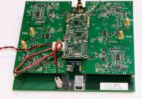
This step is pretty easy. Just place ClockTamer as shown on the picture bellow to fixate it inside of the USRP1 and connect the power cord to the USRP1's fan connector. If you don't have J24 connector, you have to find some other place for your ClockTamer to be fixated. If you do so, make sure to not short-circuit any wires on the ClockTamer or the USRP1.
Connecting the USRP1's fan
If you have removed the power limiting resistor from the fan power connector (see above), then you can connect the USRP1's fan to the ClockTamer, as shown on the picture.
Testing
   Power on your USRP1.
   If you ClockTamer is NOT connected to miniUSB, it should NOT have its LED lighting. If your ClockTamer IS connected to miniUSB, its LED SHOULD blink once and then light continuously.
   One of USRP1's LEDs should blink fast.
   Use some application from GnuRadio or UHD to check that you can get data from your USRP1 or send data to it as usual. We prefer to use usrp_fft.py for this purpose.
Referensi
- http://shop.fairwaves.ru/clock-tamer
- http://code.google.com/p/clock-tamer/wiki/ClockTamerUSRPInstallation
Pranala Menarik
Persiapan
- USRP: High Precision Clock
- USRP: Menyambungkan ClockTamer ke USRP1
- USRP: Instalasi Board
- OpenBTS: GIT Source Code
OpenBTS 2.6
- GNURadio
- GNURadio: Ubuntu Install
- GNURadio: Spectrum Analizer GSM
- GNURadio: Mengubah board RFX1800 menjadi RFX900
- GNURadio: Programming Untuk Pemula
- OpenBTS: Ubuntu Install
- OpenBTS: Konfigurasi
- OpenBTS: Kalibrasi
- OpenBTS: Konfigurasi Asterisk untuk OpenBTS
- OpenBTS: Menjalankan smqueue
- OpenBTS: Mengoperasikan BTS
- OpenBTS: Tampilan di Nokia saat pakai OpenBTS
- OpenBTS: Operasi 1800 MHz
- OpenBTS: Beberapa Tips
- OpenBTS: USRP2
- OpenBTS: Amplifier
- OpenBTS: SMS
OpenBTS 2.8
- GNURadio: Ubuntu 11.10 Install *NOT RECOMMENED*
- GNURadio: Ubuntu 11.10 instalasi menggunakan Repo NOT RECOMMENDED
- GNURadio: Ubuntu 11.10 Instal GNURadio 3.3.0
- GNURadio: Ubuntu 11.10 Install dari GIT GNURadio
- OpenBTS: Ubuntu 11.10 Install
- OpenBTS: 2.8 dari SVN Install RECOMMENDED
- OpenBTS: 2.8 Instalasi Real Time Asterisk
- OpenBTS: 2.8 Konfigurasi
- OpenBTS: Database SQLite
Ettus E110
- OpenBTS: E110 Cara Login
- OpenBTS: E110 Install Image di MicroSD
- OpenBTS: E110 Cek Daughter Board
- OpenBTS: E110 Mengubah Master Clock
- OpenBTS: E110 Bekerja dengan opkg
- OpenBTS: E110 GNURadio
- OpenBTS: E110 Instalasi OpenBTS
- OpenBTS: E110 Instalasi OpenBTS 2.6 *NOT RECOMMENDED*
Lain Lain
- Membuat Base Station GSM Open Source
- Teknologi Selular
- GSM: Daftar Channel Frekuensi
- Wireless Internet
- OpenBSC
- AirProbe
- Base station subsystem
- GSM
- Asterisk
- Mobile phone
Catatan Legal dan Pendukung
- Siapa Bilang OpenBTS Ilegal?
- OpenBTS: Catatan MNC dan MCC Indonesia
- OpenBTS : Alokasi Frekuensi Operator GSM Indonesia
