Difference between revisions of "Antenna: Membuat CoaxTrap"
Onnowpurbo (talk | contribs) |
Onnowpurbo (talk | contribs) |
||
| (One intermediate revision by the same user not shown) | |||
| Line 126: | Line 126: | ||
* http://www.qsl.net/on7eq/projects/coaxtraps.htm | * http://www.qsl.net/on7eq/projects/coaxtraps.htm | ||
| + | |||
| + | |||
| + | ==Pranala Menarik== | ||
| + | |||
| + | * [[Coaxial trap antenna]] | ||
| + | * [[Antenna: Membuat CoaxTrap]] | ||
| + | * [[Antenna : TRAP-dipole untuk 20m dan 40m band]] | ||
| + | * [[Antenna: TRAP-dipole Multiband]] | ||
| + | * [[Antenna: Rancangan TRAP-dipole 40m 20m 15m 10m]] | ||
Latest revision as of 16:01, 27 September 2012
Sumber: http://www.qsl.net/on7eq/projects/coaxtraps.htm
Some hints/tips on how to assemble nice COAX TRAPS !
Before we start to assemble our traps, here some general info as introduction :
- Coax traps are cheap, easy to assemble in a reproducible manner, very rugged, perfect for portable or permanent operation, on dipoles, inverted-V's etc.
- If made with RG-58 C/U coax, can handle easily up to 500w PEP (750w max) .... or 1.000w PEP (1.5 kW max if carefully constructed) if made from RG-400 with TEFLON dielectric, which withstands heat very well.
- Coax traps do not exhibit a very high Q-factor ... so are quite 'lossy', compared to air wound coils with high quality capacitors, but:
- High-Q coils are not suitable for high power operation: due to the high Q, very high voltages will be produced, with the risk of arcing, and the need for special capacitors (able to withstand high voltages and currents). In fact, if you intend to operate with high power (> 200w), do not aim for a high-Q trap !
- A dual-band dipole with the 'best traps of the world' has about 0,3 dB total loss due to traps, this on both bands (so either in pass-through or blocking mode, loss seems quite the same)
- Same dipole antenna with coax traps would have about 0,6 dB total loss - the double, but a negligible difference on the S-meter of your DX correspondent!
- The exact resonance frequency of the trap is important to define by construction. If you operate the trap at it's effective resonance frequency, you will have more losses, about 1,6 dB total loss for same dipole antenna. Again, this is not a dramatic figure thinking of our S-meter, but will definitely cause problems at high power, because all losses are dissipated as heat in the traps: at 500 W 0,6 dB = 37w in each trap, but 1,6 dB = 110 W (note : the undersigned has tested this and melted a trap under these conditions HI). So NEVER adjust your trap on a frequency in the middle of the band it was designed for ! I tested my traps with 500w continuous power during 10 minutes, they get 'hand-warm', but do not melt any more ...
- By mistuning slightly the trap, you have no significant degradation of antenna performance or more critical tuning (narrower bandwidth or so ...).
- Coax traps have the effect of shortening the antenna length of all subsequent portions of the antenna, therefore narrowing the bandwidth of these. Should this be a problem, it can be compensated easily by adding 'capacity hats' at the end of these sections, even consisting of 2 small wires of 20 cm mounted in 'T'.
- If you are using high power (500w or more), do not use any hardware which is subject to magnetic fields (like zinc anodized iron), but use metal which is A-magnetic, like stainless steel, brass or copper. This because the trap will cause a very intense magnetic field while resonating, and induce stray currents in surrounding (lossy) magnetic metals, enough to heat them up to such extent that they will melt through the PVC tube (= see my experience below) !
Now let's go to work ! Here are the step by step instructions for 20m (and 40m) (and 15m) band traps:
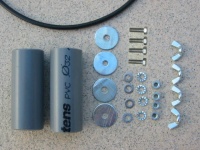
Bill of Materials (for 2 traps):
- 2 PVC sewage pipes, Outer Diameter (OD) 32 (50)(32) mm, 80 (95)(80) mm long each, thick walled (3mm) and resistant to heat (95°) version.
- 4 bolts with nuts, M5x15 or M5x17 (zinc anodized or Stainless Steel for permanent use)
- 4 'grower' M5 (teethed washers)
- 4 washers M5 (zinc anodized or Stainless Steel for permanent use)
- 4 butterfly nuts M5 (zinc anodized or Stainless Steel for permanent use)
- 4 big washers M5 , outer diameter 25mm. Use ZINC ANODIZED IRON if you want to solder directly on them, if you use copper or stainless steel , you will need a eye lug to solder the coax and connect to the M5 bolts.(recommended for high power).
- 186 (306)(134) cm COAX CABLE type RG-58 C/U (the type is critical, use C/U version, to have same capacitance per meter and power handling)
Preparation of the pipes:
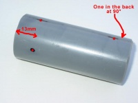
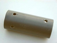
- Mark 2 holes in-line (these are for the bolts), at 13 (15) (13)mm from each end of pipe
- Mark 2 holes (these for coax), at 13mm from each end of pipe, and for 20m trap 90° on each side of the two holes for the bolts (so the coax holes will be 180° opposite) / For 40m trap, at 32mm distance along the circumference, on each side of the marks for bolt holes. For 15m, same construction as for 20m.
- Drill all 4 holes with 5mm and remove sharp edges with a trimmer, especially for the coax holes
Preparation of the the 4 big washers:
- These are used for mechanical strength and connecting the coax ends to terminal bolts
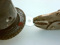
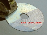
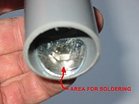
- Remove zinc anodization on 1/2 of washer surface (as soldering is very difficult and unreliable on anodized zinc). Use a grinder or file.
Now this will be the area where we will solder the coax ends
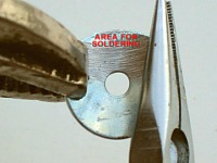
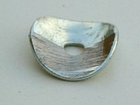
Using 2 pliers, bend the washer so that it will fit inside the PVC tube. Keep the area for soldering as depicted!
This will be the result (4 pces), adjust till they nicely fit inside the PVC tube.
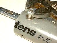
Now insert the 4 big washers in the tube ends, keep the area for soldering on the outer side, and insert the M5 bolts.
Now put the small washer and M5 nut on the bolts and tighten very well with appropriate tools.
We are now ready to start to wind our coax coils !
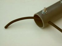
Take 93 (153) (67) cm of RG-58C/U coax for each coil. Insert approx 10 cm in the hole for the 'start'. RG-58C/U will just pass in a 5mm hole.
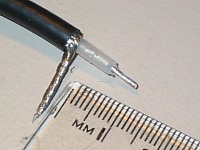
Remove insulation on 15mm of the end passed through pipe and prepare tail like shown
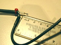
On the shield, solder a small hookup wire length 120mm about (take at least same gauge as coax center wire) and cover with heat shrink tube. Put a small nylon fastener 3mm after the start of coax outer jacket (here in the picture in red).
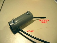
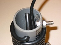
Now gently retract the coax in the tube, while inserting the hookup wire till it comes out of the tube on the other side, and the coax cannot be pulled out any more (nylon fastener)
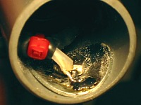
Now solder (a 60w iron should be OK) the coax center on the big washer. Make sure you have a good bond, but do not overheat as the coax / PVC will melt...
Now start to wind the coil !
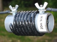
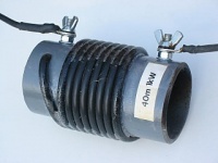
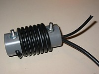
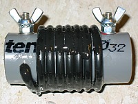
- tightly wind the coax around the PVC tube, till you have 7,5 turns (8,7 turns) (5,5 turns widely spaced, spread over tube), where the coax will enter the PVC tube again
- spread evenly the windings for 20m trap, keep them 'tight' for 40m trap
- make sure the coax outer windings are at least 3mm from the connection bolts/nuts
Use the short remaining end of coax to pull is as much as possible inside the tube and have windings sitting tight. Then cut off the coax so you have 20mm left inside the tube.
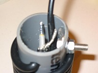
Using a cutter knife delicately around outer jacket, remove insulation on about 15mm and prepare coax ends like shown.
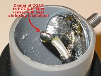
- Solder the coax shield to the big washer
- Solder the coax centre to the hookup wire , which you will have cut till desired length (make it as short as possible)
- Cover this solder joint with heat shrink tube, immediately after heating it up, squeeze firmly with pliers the free end to seal off the tube.
- important: check if both M5 nuts are still well tightened (they will loosen with the heat !)
Your coax trap is now ready to be tuned !
How to tune the traps ?
- Use a grid-dipper (but must be accurate to 100 kHz at least)
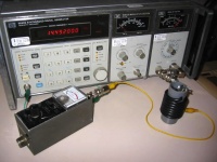
- Use a signal generator and put the trap in series with a RF voltmeter, a field strength meter input, .... and look for minimum signal (= resonance)
- Use a transceiver with adjustable low power (5w ?), connect the trap in series with a power meter/dummy load, or a small bulb (like of bicycle rear light), and look for minimum lighting up (= resonance)
- Tune both traps at 15 (7.3) (22) MHz by playing with the coil windings (closer to each other = lower frequency). You will see that the dip is quite broad.
- Try to distribute the windings evenly till all looks nice - this will as well distribute the dissipated heat evenly and prevent arcing. Make sure the coax outer windings remain at least 3mm from the connection bolts/nuts.
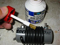
Once the resonance is OK and the trap is looking fine, apply PVC glue (this glue is used for mounting PVC tubing, it is clear, dries in minutes and becomes quite hard after hours) on the windings, especially on the outer turns of the coil, and a couple of strokes in the longitudinal direction. Liberally apply 2 or 3 coats of glue as well on the coil inside (soldering points, coax ends, big washers etc. to weather protect these elements). The recheck the resonance point : it will not have moved due to the glue.
Put the 5mm 'grower' washers and the butterfly nuts in place (with some Vaseline grease as protection against rust) : your COAXTRAP is now ready ! Apply a label indicating the band it has been designed for as the 'finishing touch' !
Referensi
