TinyTrak DK7IN
Sumber: http://www.dk7in.de/TinyTrak_e.html
The circuit presented here could generate an APRS signal with very little effort. Starting point was the TinyTrak from Byonics, where all functions are done with a microcontroller. The position data in NMEA format ( $GPRMC ) delivered from a GPS receiver is decoded and a 1200 bps packet radio signal is generated from it. This can be fed directly into a transmitter without the need of a TNC. Because of the simple circuit a decoding of received APRS signals is not possible.
The APRS interface has a serial interface for connecting the GPS or for programming several parameters with a computer. The main new features compared to Byonics TinyTrak besides some power supply variations are speed dependable beacon rates and beacon transmissions at major course changes.
Circuit
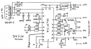
Heart of the circuit is a Microchip PIC16F84-10/P microcontroller that also generates the neccessary frequencies for the packet radio signal. The 10 MHz version has to be used because the 4 MHz version is too slow for generating the audio frequencies.
The circuit is equivalent to the TinyTrak design with a few hardware and firmware additions. The knowledge of the TinyTrak documentation is helpful and silently assumed...
I could not get a ceramic resonator, therefore I used a 10 MHz crystal, which needs two additional 22pF condensors.
An additional 100nF condensor from the common point of the four D/A converter resistors to ground slightly improves the shape of the audio signals.
A Jumper allows to connect a 2k2 resistor for PTT control over the MIC line as needed for most handies. An installed jumper gave no problems with my mobile transceivers FT-90R and TM-733, but who knows. A 100nF condensor from the base of the PTT transistor to ground avoids problems with HF interference.
At pin 11 of the microcontroller a key to ground could be connected, which allows to transmit a beacon immediately.
Besides the fixed beacon rates my extended firmware supports a smart beacon control. With that the beacon rate changes depending on your speed, according to two selectable tables.
| Maximum speed | < 4 km/h | > 4 km/h | > 11 km/h | > 24 km/h | > 50 km/h | > 100 km/h | > 150 km/h |
|---|---|---|---|---|---|---|---|
| S2 on: beacon every | 25 min | 4 min | 120 sec | 60 sec | 30 sec | 20 sec | 10 sec |
| S2 off: beacon every | 30 min | 5 min | 160 sec | 80 sec | 40 sec | 30 sec | 20 sec |
Relevant is the maximum value of the speed since the last beacon transmitted.
For a better track accuracy at street edges a beacon will be transmitted if there is a major change in the driving direction, while the speed is more than 15 km/h. That is, if the current course differs more than 40 degrees (60 ° if S2 is off) from the course at the time the last beacon was transmitted. The beacon will be delayed, if the last beacon was less than 10 sec ago.
Sometimes I'm asked if the altitude could be transmitted too. Yes, in principle. The $GPRMC sentence now used does not contain the altitude, so I would have to look at $GPGGA too. I already have optimized the code somewhat for the recent changes, but now only 21 bytes are left in program memory. May be I get a solution some day... but I don't know.
In the meantime Byonics added the transmission of height to the original TinyTrak, and I think their memory then was full too. Now I was a beta tester for a new TinyTrak-II with a microcontroller with more memory. Besides the altitude the new TinyTrak-II now also has smart beaconing and corner beacons like I did it before. This replacement ship should be available from Byonics after the 2001 Dayton Hamvention. So if you don't like to do it yourself...
Power Supply
For reduced current consumption, instead of the 78L05 I used a National Semiconductor LP2950, a low power, low dropout voltage regulator. I left out the power LED and the circuit needs around 5mA with illuminated GPS LED.
Deccoupled with a few diodes the circuit can be powered via the handshake lines of the serial interface. Instead of the 1N4148 Schottky diodes L103B with lower forward voltage could be used. With that changes there is no need for an external power supply during parameter programming. It also can be powered from the transceiver, as an example there are +9V on the 6 pin microphone connector of my Yaesu FT-90R. If neccessary, an external power supply can be connected via the GPS connector as shown further down.
If used in a car it might be neccessary to insert a diode into the ground line direct behind the D-Sub socket. With that a ground loop over the microphone line could be avoided that could lead to a distortion of the audio signal by superimposed generator noise. The logic levels of the GPS signal are not so vulnerable.
For protecting the microcontroller pins used for the serial interface, a 330R resistor was inserted into the transmit line. In combination with the 10k resistor a Schottky diode cuts negative voltages on the receive line and a 5.1V zener diode limits the input voltage to +5V.
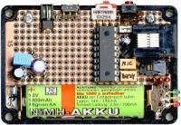
For another circuit, designed especially for portable use, a DC/DC convertor generates 3.3V from a single AA cell. The microcontroller works without problems with that low voltage but needs much less current than with 5V. For the serial line protection now a 3.0V zener diode is used (instead of 5V) and the resistors in line with the LEDs were reduced (red 820R, green 680R).
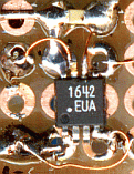
The DC/DC convertor was built with a Maxim MAX1642. With a 1800mAh NiMH accu this circuit will run for about 150 hours.
Carrier Detect
The carrier detect circuit used by TinyTrak could not distinguish between signal and noise. Because the squelch on my Kenwood TM-733 is not working on the data port I could not use the original circuit (10k trimmer between "A" and "B"). If this part is left out, the transceiver could send even if the channel is busy. Of course, especially with a lot of APRS stations this is annoying. If you have a working squelch circuit the simple version with the trim poti is sufficient.
The simple circuit works relatively well, if used with the internal squelch of the transceiver and connected to the speaker output. But then you always have to adjust the squelch and volume control. When using the data connector, my Kenwood TM-733 works without the XR2211, but my Yaesu FT-90R needs the carrier detect circuit.
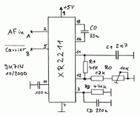
With an Exar XR2211 a better carrier detect circuit can be built that can distinguish between signal and noise.
R0 and C0 determine the center frequency, R1 the bandwidth, RD and CD sets the time constant of the lock detect filter. R0 is in the area of 15k to 17k in my circuits.
The circuit should respond if the input frequency falls between 1200 Hz and 2200 Hz. The dimensioning is a little bit critical, for more information have a look on the data sheet and application note TAN-008 and experiment with the values.
The circuit should be inserted at points "A" and "B" in the above schematic.
With this circuit part the current consumption increases to around 10mA, a little bit too much for taking the power from the serial lines. Because the TinyTrak software only sets one handshake line (RTS), the voltage breaks down to 3.7V during programming. But it works! Otherwise (e.g. with notebooks) an external power source should be connected.
Construction
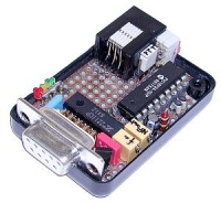
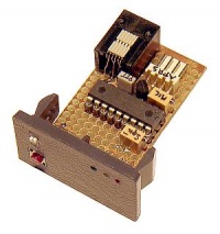
First a note for those, who are not so experienced. The original TinyTrak is sold as a kit with already programmed microcontroller. In Germany WiMo has it. The circuit was built on an experimentation board and fits into a small plastic case.
I used a 6 pin Western socket for the transceiver side as it is used on my FT-90R for the microphone connector.
When two contact strips are used instead of a conventional IC socket, a low profile crystal can be placed directly under the microcontroller. All other parts are located on the bottom side of the board mostly as SMD parts.
Another circuit (without XR2211) was built behind an unused switch cover in my car.
In the meantime a carrier detect circuit with a XR2211 was added on the remaining free space, so I now could also use my Yaesu FT-90R in the car.
The two tiny SMD switches are used for setting the mode and with the key a beacon could be transmitted manually.
Here a DC/DC convertor produces 3.3V from a single cell. With a 1800mAh NiMH accu this circuit runs for about 150 hours, so it is best suited for portable use.
Microcontroller Programming
A new microcontroller first has to be programmed with suitable firmware, that means a program has to be loaded that analyses the GPS data and generates the APRS signals. You can find information for building programmers on the web, also see my microcontroller page. Here is my current firmware V1.6. Some electronic parts companies not only sell microntrollers but also can do the programming for you. If you encounter problems reading the HEX file with some homebrew flashers with Windows software, try opening and saving the HEX file with a text editor first.
Adjustments
The audio level has to be adjusted for correct modulation of the connected transceiver and the PTT jumper should be set for handies (PTT via MIC input).
For checking the modulation or the frequency shift the circuit can produce some constant frequencies. This can be controlled with my configuration program or by entering special commands with a terminal program (4800 baud, 8N1). Using the last another arbitrary character ends the tone and reinitialises the circuit.
- ESC T 0 generates a 1200 Hz tone
- ESC T 1 generates a 2200 Hz tone
- ESC T M generates a mixed 1200/2200 Hz tone
A signal generator is advantageous for adjusting the XR2211 carrier detect circuit. The center frequency should be set with the trimmer, so that the circuit responds in an area somewhere from 1150 Hz to 2250 Hz. If the bandwidth is not correct R1 has to be changed (I use 47k || 330k).
With the simple circuit the 10k potentiometer will be adjusted, so that the carrier LED is just not illuminated. You have to set squelch and volume on your transceiver.
Settings
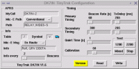
The programming of the parameters (call, path) is done with a Perl/Tk script under Linux. It also displays the icon of the selected symbol and supports the generation of the test frequencies. Those Windows users, who don't want to experiment with Perl, Tk and the needed modules, can use an older version of the original setup program TinyTrakConfig.exe from Byonics.
If all works, Version should display the version string of the connected TinyTrak. At least at the second time, if powered from the serial line. The fixed beacon rate could be set in 10 sec steps, the TxDelay with a resolution of 6.6 ms.
The mark and space frequencies can be adjusted slightly with the Calibration parameter. For Bell 202 they should be 1200 and 2200 Hz, but because of system limitations their distance is a bit too high.
| Calibration | 36 | 40 | 50 | 58 | 60 | 63 | 70 | 80 | 90 |
|---|---|---|---|---|---|---|---|---|---|
| Frequency 1 [Hz] | 1199 | 1197 | 1191 | 1187 | 1186 | 1184 | 1180 | 1175 | 1169 |
| Frequency 2 [Hz] | 2249 | 2244 | 2234 | 2225 | 2223 | 2220 | 2212 | 2202 | 2192 |
Here the influence of the calibration factor on the measured frequencies is shown. For the smallest symmetrical percentage error I choosed a value of 58.
The two switches select the operation mode. With switch S1 open, a fixed beacon rate will be used, if closed smart beaconing is enabled, where the beacon rate is controlled by your speed and direction changes.
With fixed beacon rate, S2 decides whether to use the primary (S2 on) or the secondary timing (S2 off). With smart beaconing and S2 closed, beacons will be transmitted more often (upper row in speed table) and direction changes of more than 40 degrees trigger a beacon. Otherwise transmissions occur less often (lower row) and a direction change has to be more than 60 degrees. S2 always determines the TxDelay according to the primary or secondary timing.
The carrier detect LED at pin 17 is illuminated if another station is transmitting. The GPS LED at pin 18 is on with valid data from the GPS receiver and blinks while receiving GPS data without a valid position. The PTT LED is on while the transmitter is keyed. During initialisation at powerup the yellow and green LEDs are blinking three times followed by a beacon. But automatic beacons will only be transmitted if valid NMEA data from the GPS receiver is received.
Connection
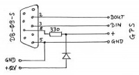
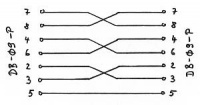
My cable for the GPS receiver has a female DB-09 connector, so it matches directly with the computer. The power supply of the GPS is done over this interface cable and also the APRS interface is supplied through a 220R to 330R resistor.
In my case I decided to also use a female connector for the APRS interface for direct computer interfacing, so an adapter cable (null modem) is needed for connecting to the GPS receiver.
Referensi
- http://www.dk7in.de/TinyTrak_e.html
- http://www.dk7in.de/TT-in-16.zip - firmware
- http://www.qsl.net/zl1vfo/tinytrak/tinytrak.htm
- http://www.qsl.net/zl1vfo/tinytrak/tinytrak1.02.zip
- http://www.qsl.net/zl1vfo/tinytrak/tinytrak1.4.zip
- http://www.qsl.net/zl1vfo/tinytrak/tinytrak1.4.hex
- http://www.qsl.net/zl1vfo/tinytrak/tinytrak3a.zip
- http://www.qsl.net/zl1vfo/tinytrak/tinytrak3.zip

