Final: Pembatas Arus Final
Sumber: http://www.g0kla.com/scpa/SimpleCheapPA.php
I built this amplifier so that I could be heard above the QRN and QRM on 40 meters in the evening. I found I could work stations in about a 200km radius during the day with 5 - 10 watts, but at night I could work no one at all.
Many people build low power equipment and find amplifiers difficult. I have had my fair share of difficulty with obtaining high power. In fact, it was harder for me to create the 5-10 watts of drive that this amplifier needs, than is was to build and test this amplifier. My advice is to build straight forward building blocks and test each one to make sure that it is working. For example the final stages in the Gateway 40, which typically drives this amplifier, used Fig 2.93 in Experiemenal Methods in RF Design. It took me a while to get that curcuit to work because I had used a wire wound resistor in one of the emitters by accident. I asked advice on the yahoo EMRFD group and finally got it working. I followed that driver with Fig 2.98,, which uses a single IRF510 and generates 5 watts easily, 10 watts with higher supply voltage.
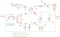
The circuit below is an old one, repeated many times. It was inspired by Fig 2.101 in EMRFD, the AA3X amplifier, but there are well documented examples online. I ended up following an article by Mike Kossor, WA2EBY, published in QST in March 1999, but I kept the design simpler and did not look for the flat, maximum gain across all bands that he was after. This was an experiment for me and aimed mainly at 40 meters.
Current Sense Circuit
I destroyed many IRF510 FETs during testing. In fact I blew a small hole in one and another into several pieces. It was quite a shock when the first one was destroyed because it made a loud noise like a rifle being fired.
Once I got tired of replacing the FETs, I built a current sense circuit, which shuts off the bias once the amplifier draws more than about 3 amps from the PSU. I think this circuit is essential. You can build it into the Power Supply or into the Amplifier. I built it into the Amplifier because the power supply, which is also homemade, does not limit until 7 amps. With the current limit circuit the amplifier now survives transmitting into any SWR from an open circuit to a short.
The amplifier
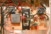
Back of Simple Cheap PA I built the amplifier ugly style using small heatsinks flush against the copper board. The whole board then acts as a heat spreader as well as the ground plane. This is not the approach that others recommend. Much bigger and more expensive heatsinks are usually found in these amplifiers. This works for me. I don't have a fan, the heatsinks are inside the box and everything survives normal SSB operation well. It was what I had to hand at the time. If you have a better heatsink in your junkbox then use it. Otherwise these heatsinks are very cheap at Mouser.com
One key to success with this amplifier was an input attenuator. It made sure that the radio saw a clean 50 ohm load. Occasionally, if the load was mismatched, the PA driver (in the radio) would oscillate or produce broadband noise. Adding an attenuator worked well and solved this. If you find that your amplifier is producing broad band noise and oscillating, check to see if it is the driver, rather than the amplifier itself.
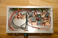
The box contains the amplifier board and the low pass filters. I designed the low pass filters with ELSIE, which comes free with the ARRL Handbook. I calculated the number of turns needed on the torroids with a spreadsheet like this one. So far I have only constructed filters for 20M and 40M because those are the only bands I can transmit on. I tested them with a signal generator and my Power Meter.
You can see that the amplifier is in a no frills box from Mouser.com. The torroids are all from Amidon. Those in the amplifier use type 43 material. The output transformer is one of their solid ferrite blocks. It is probablly overkill for this power level.
Performance
This amplifier works well and I get good reports on the air. If I drive it too hard though, it distorts, so I have to be carefull with the drive level. The IRF510 is not the cleanest device, but a higher supply voltage (I use 30 volts) and push pull configuration all helps. I have worked several stations in South American and in Europe with this setup. I went from below the noise to just about workable with this power level on 40 meters ssb.


