FTTH: Arsitektur
Sumber: https://www.technopediasite.com/2018/12/ftth-components-and-general-architecture.html
Technopediasite .
Menu Home » Splitters » FTTH Components and General Architecture
Home FTTH Components and General Architecture ODF OLT POS Splitters FTTH Components and General Architecture FTTH Components and General Architecture
Techno Pedia December 23, 2018 FTTH Components and General Architecture, ODF, OLT, POS, Splitters,
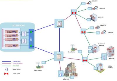
The main components and general architecture of the FTTH network at any telecom operators include the Optical Line Terminal (OLT), Optical Distribution Frame (ODF), Passive Optical Splitter (POS), Fiber Distribution Terminal (FDT), Fiber Access Terminal (FAT), Fiber Terminal Box (FTB), Optical Distribution Box (ODB), Optical Splitter Box (OSB), Optical Network Unit/Terminal (ONU/ONT). These all components are the main component to built a FTTH networks.
The Access Node is located in the Central Office, wherein the OLT, the ODF and the first POS stage are housed. From the Access Node the Feeder Network is based in a number of Feeder routes and cables that interconnects the FDTs in a ring topology to provide network resiliency. The FDT is the aggregation element that performs the Remote Node functions. The FDT houses the second POS stage, although some fibers are reserved to pass-through it without splitting.
Ahead of the FDT, the Distribution Network approaches the network to the end users by means of a number of Distribution Cables. Along the path of each Distribution Cable, a number of FATs are connected. The FATs perform the Dispersion Node functions. From the FAT, the Drop Cables provide individual connectivity to each building in a star topology, either Single Dwelling Units (SDU) or Multi-Dwelling Units (MDU). Some buildings (e.g. key accounts customers, government) can have a dual homing connectivity to two separate FATs.
ACCESS NODE FOR FTTH
The Access Node is the starting point of the optical access network in its fiber path up to the end user. The function of the Access Node is to house all active transmission equipment, manage all fiber terminations and facilitate the interconnection between the optical fibers and the active equipment. The size of the Access Node is determined by the size and capacity of the FTTH area to serve in terms of users and future upgrades.
Access Nodes are usually housed in Central Offices (CO) of telecom operators or in GSM containers. To serve remote areas, it can be also housed in an outdoor cabinet.
The network elements contained in the Access Node are:
- The Optical Line Terminal (OLT).
- The Optical Distribution Frame (ODF).
- The Passive Optical Splitter (POS), but not always.
OPTICAL LINE TERMINAL (OLT)
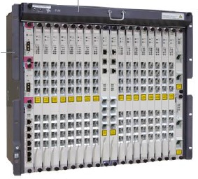
The OLT is the Central Office switch and aggregation equipment for GPON systems. An OLT isa subrack chassis that contains a number of slots to install GPON service boards, upstream boards, control boards and power boards.
Service boards provide 8 or 16 GPON ports depending on the model and vendor. Each GPON port serves up to 64 end-users, but a lower density of users per port is also possible varying the split ratio. The OLT subrack is commonly offered by vendors in 3 sizes: Large (16 to 18 service boards), Medium (6-8 service boards) and Mini (2-3 service boards) in order to adapt to different size scenarios.
The main function and features of the OLT are:
- Interfaces the ONU/ONT in the downstream direction of the PON.
- Interfaces the core network for traffic aggregation and transport.
- Controls service policy.
- Manages security and authentication policy.
- Reports ONU/ONT status.
PASSIVE OPTICAL SPLITTERS
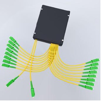
Passive Optical Splitters (POS) perform basically a 1:N function (where N represents a splitting ratio from 2 to 64). A 1xN optical power splitter is a passive device that splits the power of the optical signal carried by a single input fiber into N output fibers. The input optical power is usually distributed with uniform power over the N output fibers.
Moreover, Passive Optical Splitters performing a 2:N function are also available. In that case, instead of a single input port, two input ports are provided. The optical signals carried by both input ports are split into the output ports at the same time. Passive Optical Splitters with 2 input ports are frequently used to build resilient architectures based in diversity paths and is the option selected at telecom operators.
Splitters are actually coupler devices as well because they combine the signals in the upstream direction as well as they split the downstream.
A specific 1xN split ratio in a PON can be achieved in two main ways: ➤Single stage, built with a single optical splitter. ➤Multiple stages or distributed splitting, built with the cascade of several splitters of lower range located in different locations. In practice, 2 stages are very common, but PON rarely exceeds 3 splitting stages.
Inserting optical splitters allows sharing efficiently the feeder network and the OLT port between a number of end users. However, splitters also head to the following consequences:
⏩Splitters create a broadcast distribution network. The same optical signal is received by all ONTs. Security and confidentiality concerns might need to be addressed. ⏩Splitters limit the optical reach of the transmission. As the incoming optical power is split in several branches, the splitter insertion loss is high and the optical power available in each branch is considerably low, limiting the optical distance to reach. The higher the split ratio 1:N, the less the power in every branch and the lower the optical reach. ⏩Splitters limit the bandwidth available for each user. Bandwidth is shared among all the users connected to a particular splitter. The higher the split ratio, the less the average available bandwidth per ONT.
While selecting the PON splitter ratio 1:N, there is a trade-off between bandwidth per user and optical reach in one side, and network cost per user in the other side. As a rule of thumb, doubling the splitter ratio halves the bandwidth per user and reduces the optical reach by 10 km. Most of the commercial PON systems built today have a splitter ratio of 1:32 or 1:64.
Splitters are critical devices in PONs. Its quality has a relevant influence in the PON performance and optical reach. Splitters constructed with PLC technology are preferable for their insertion loss and loss uniformity figures and for their wider operation wavelengths.
Optical splitters are provided pre-connectorized with an LC/APC connector at both ends.In FTTH architecture, optical splitters may be placed in different locations:
- Central Office, besides the OLT (housed in the ODF rack).
- Fiber Distribution Terminal (FDT).
- Fiber Access Terminals (FAT). Only in exceptional cases.
- Optical Splice Box (OSB) housed in Multi Dwelling Units (MDU) buildings.
ODF AND OSF
The Optical Distribution Frame (ODF) is the network frame where the fibers from the outdoor cables are terminated and become available to interface with the active equipment or patching.
Typically, outdoor cables are terminated in the underground facility that provides the entrance to the Central Office. From there a fire retardant ISP transfer cable is spliced to the outdoor cable and transported up to the ODF. In some cases, the outdoor cable itself terminates at the ODF.
The ODF offers flexible patching between active equipment ports or splitters and the outdoor cable termination. Fibers are identified and stored in physically separated housings or shelves to simplify fiber maintenance and to protect or avoid accidental interference to fiber circuits.
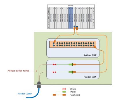
Each fiber from the Feeder cables is spliced to a connectorized pigtail and terminated in an LC/APC adapter at the front of the ODF panel.
Adapter: A device mounted on the patch panel, used to mechanically align, couple and mate or join two plug-in optical connectors of patch cords and pigtails. This is intended to provide a readily available or separable connection between two optical fibers.
Connector LC/APC: A device for providing a readily separable plug-in connection between two optical fibers using a matching adapter. LC is a type of optical connector and APC (Angle Physical Contact) is a type of polish fiber end-face.
Patchcord: Single fiber cable pre-assembled with a connector at both ends, type LC/APC.
Pigtail: A short length of single fiber cable pre-assembled with a connector at one end (e.g., LC/APC), and the other end being connected to the fiber cable by fusion splicing.
The ODFs can be supplied with a number of modular capacities, from 24 to 288 fibers, in order to fit to the size of the fiber optic cable to be terminated.
- High-Density ODF (HD-ODF) has a capacity of up to 2016 fiber terminations arranged in 144 fiber panels (3U).
- Ultra-High Density (UD-ODF) has a capacity of up to 4032 fiber terminations arranged in 288 fiber panels (3U).
The Optical Splitter Frame (OSF) is a modular encapsulation of optical Splitter(s) in a rack mountable unit. Usually in 1U unit 2x32 splitters can be accommodated.
Below image displays the connectivity options at the ODF, either if an optical splitter is included in the path or not. The number of ports in the splitter can vary depending on the access scenario.
Tags # FTTH Components and General Architecture # ODF # OLT # POS # Splitters


