IPv6: Routing Overview
Sumber: https://www.tutorialspoint.com/ipv6/ipv6_subnetting.htm
In IPv4, addresses were created in classes. Classful IPv4 addresses clearly define the bits used for network prefixes and the bits used for hosts on that network. To subnet in IPv4, we play with the default classful netmask which allows us to borrow host bits to be used as subnet bits. This results in multiple subnets but less hosts per subnet. That is, when we borrow host bits to create a subnet, it costs us in lesser bit to be used for host addresses.
IPv6 addresses use 128 bits to represent an address which includes bits to be used for subnetting. The second half of the address (least significant 64 bits) is always used for hosts only. Therefore, there is no compromise if we subnet the network.
16 bits of subnet is equivalent to IPv4’s Class B Network. Using these subnet bits, an organization can have another 65 thousands of subnets which is by far, more than enough.
Thus routing prefix is /64 and host portion is 64 bits. We can further subnet the network beyond 16 bits of Subnet ID, by borrowing host bits; but it is recommended that 64 bits should always be used for hosts addresses because auto-configuration requires 64 bits.
IPv6 subnetting works on the same concept as Variable Length Subnet Masking in IPv4.
/48 prefix can be allocated to an organization providing it the benefit of having up to /64 subnet prefixes, which is 65535 sub-networks, each having 264 hosts. A /64 prefix can be assigned to a point-to-point connection where there are only two hosts (or IPv6 enabled devices) on a link.
SUMMARIZATION
We’ve mentioned summarization as well as its synonym aggregation (both sometimes referred to as supernetting) at different times in the previous chapters. It’s a subject that should already be familiar to us from designing, building, and running IPv4 networks. But it’s probably a good idea to review it in the context of our current IPv6 subnetting discussion.
Simply stated, summarization is the combining of smaller networks into larger ones. Recall that only contiguous networks of the same size (i.e., bit length) can be summarized:
/64 + /64 = /63
/63 + /63 = /62
/62 + /62 = /61
etc. Summarization provides multiple benefits:
- It reduces the total number of routes (and routing table entries) that routers in the network must learn and keep state information on. This is by far the most important benefit of network aggregation. By reducing the number of routes that routers must learn and keep track of, memory and CPU resources are preserved, potentially delaying costly router upgrades or replacement. A reduced number of routes can also lead to faster convergence and improved performance of the network as fewer network prefixes mean that updates between routers can be sent and processed faster.
- It can reduce the administrative overhead associated with tracking address assignments. Aggregation can reduce the number of entries in network management and IPAM systems, reducing the amount of overall data network operations personnel and process must track and potentially reducing operational expenditures.
- It can help create well-defined network and administrative boundaries that allow us to simplify security policy and improve operations performance. Often, network aggregation correlates to well-defined administrative boundaries. This can greatly simplify the definition and configuration of security policy through ACLs and policy documentation. It can also improve network operations efficiency, leading to faster isolation and resolution of issues and problems on the network.
Nibble Boundaries A nibble is 4 bits. Since IPv6 addresses are expressed using hexadecimal characters, subnetting exclusively in multiples of four bits has several important benefits for address planning (and operations).
The first and most obvious of these is that our CIDR notation for any prefix will always be a multiple of four. For example, starting from a /64 (as that’s the smallest typical subnet size):
/64, /60, /56, /52, /48, /44, etc.
From an operational standpoint, this makes any subnetting transcription errors in configuration or documentation immediately apparent. For example:
/53, /47, /39, etc.
The next benefit is that we have a smaller possible set of subnet groups to account for, as shown in Table 4-1:.
Table 4-1. Binary nibbles n 24n 1
16
2
256
3
4096
4
65536
5
1048576
6
16777216
7
268435456
8
4294967296
As we get into our address plan design based on our network topology, it’s uncommon that we’ll have any network entities (VLANs, buildings, business units, etc.) in groups larger than 65536.
Also, much of our address planning will be focused on either the 16 bits of the individual site subnet ID (from /48 to /64) or the 16 bits of the overall organizational assignment (typically from /32 to /48, though possibly larger for the largest enterprises). As a result, the first four values (i.e., 16, 256, 4096, and 65536) are the most often used and thus most usefully remembered.
The final benefit takes a bit more explaining.
Prefix Legibility The final benefit of adhering to the nibble boundary when subnetting in IPv6 is improved prefix legibility (or, to put it another way, human-readability).
What do we mean by legibility? Let’s demonstrate with an example. Say we’ve been assigned a /48 for the headquarters site of a large enterprise. (We’ll explain in detail why we might get such an assignment in Chapter 5.)
The site has 20 buildings, and we’ve designed our plan to allocate one subnet per building. (We’ve been told to anticipate very little growth as the company is planning on moving the HQ sometime in the next two to five years.) We’ll set aside an additional subnet for infrastructure between buildings for a total of 21 subnets.
The minimum number of bits we’d need to use to support 21 subnets would be 5, which gives us a total of 32 subnets. We’ve got 11 subnets to spare in case any need arises to assign additional ones. The Ns represent these 5 bits below, while the Xs are unspecified:
2001:db8:abcd:[NNNNNXXXXXXXXXXX]::/53
Note that while this provides sufficient subnets, the resulting prefixes aren’t as immediately legible because the bit boundary doesn’t align with the 4 bits used to define the hexadecimal character in the address:
2001:db8:abcd:0000::/53
2001:db8:abcd:0800::/53
2001:db8:abcd:1000::/53
2001:db8:abcd:1800::/53
...
Continuing with our example, the abundance of addresses available in IPv6 allows us to use 8 bits (instead of only 5), which makes the hexadecimal representation of the resulting subnets much tidier:
2001:db8:abcd:000::/56
2001:db8:abcd:100::/56
2001:db8:abcd:200::/56
2001:db8:abcd:300::/56
...
For each subnet group, only one value is possible for the hexadecimal character that corresponds to the 4-bit boundary in the IPv6 prefix (in this case, a /56). This makes the resulting prefix more immediately readable.
Obviously, the use of more bits gives us more subnets: 256 in this case, 21 of which we’ll use immediately along with 235 for future use. But fewer host ID bits also reduces the number of available /64 subnets in each parent subnet. In our above example, we went from 2048 /64s available per /53 to 256 /64s available with a /56.
Visualizing Hierarchy
As mentioned in the last section, much of our address planning will be focused on either the 16 bits of the individual site subnet ID (from /48 to /64) or the 16 bits of the overall organizational assignment (typically from /32 to /48).
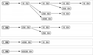
As it turns out, dividing either of these 16-bit groups along their nibble boundaries gives us a very simple way of visualizing the hierarchy available to us when defining our addressing plan. We’ll pick the typical subnet ID range to demonstrate, i.e., /48 to /64 (Figure 4-1).
To create an IPv6 subnetting hierarchy from a /48 using the above diagram, simply choose one of the four boxes and then a single path in that box from left to right.
The first box gives us four unique possibilities, as shown in Figure 4-2:
Box two provides two possible paths (Figure 4-3):
One path each is provided by the third and fourth boxes (Figure 4-4):
Adding the possibilities up, we end up with only eight paths to choose from.
As it happens, this simple expression of subnetting hierarchy will often prove more than adequate to guide a basic topology for many organizations. It strikes a good balance between the minimum amount of complexity required to instantiate operational efficiency and the simplicity to make and keep the plan extensible and flexible.
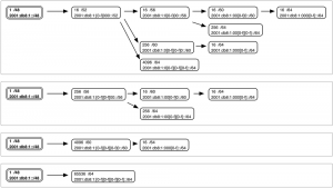
Let’s take a look at the same figure with actual subnets added for clarity (Figure 4-5):
In this figure, the range of possible values to enumerate the subnets available at that level of hierarchy is bracketed. For example, starting in the upper left-hand corner and moving to the right, we observe that the 16 /52s at that level will be enumerated by modifying the first character of the fourth hextet:
2001:db8:1::/52 (or, expanded for clarity, 2001:db8:1:0000::/52)
2001:db8:1:1000::/52
2001:db8:1:2000::/52
...
2001:db8:1:F000::/52
From there, each of our /52s could be further subnetted along one of three different paths.
The first path gives us 16 /56s enumerated by the second character (and next 4 bits) of the fourth hextet. Choosing the first /52 from the step above, we get the first group of 16 /56 subnets:
2001:db8:1::/56
2001:db8:1:0100::/56
2001:db8:1:0200::/56
...
2001:db8:1:0F00::/56
The second group of 16 /56 subnets would be:
2001:db8:1:1000::/56
2001:db8:1:1100::/56
2001:db8:1:1200::/56
...
2001:db8:1:1F00::/56
The second path gives us 256 /60s enumerated by the second and third character (and 8 middle bits) of the fourth hextet. Again choosing the first /52 subnet from our first example, we get the first group of 256 /60 subnets:
2001:db8:1::/60
2001:db8:1:0100::/60
2001:db8:1:0200::/60
...
2001:db8:1:0FF0::/60
The second group of 256 /60 subnets would be:
2001:db8:1:1000::/60
2001:db8:1:1100::/60
2001:db8:1:1200::/60
...
2001:db8:1:1FF0::/60
The final path gives us 4096 /64s enumerated by the second, third, and fourth characters (and right-most 12 bits) of the fourth hextet. Once more, starting with the first /52 subnet, we get the first group of 4096 /64 subnets:
2001:db8:1::/64
2001:db8:1:0100::/64
2001:db8:1:0200::/64
...
2001:db8:1:0FFF::/64
The second group of 4096 /64 subnets would be:
2001:db8:1:1000::/64
2001:db8:1:1100::/64
2001:db8:1:1200::/64
...
2001:db8:1:1FFF::/64
Hopefully, these images (and the method associated with them) give you a better sense of how to visualize and enumerate the subnets and hierarchy options available to you for a site. With a few uses, you’ll quickly be able to mentally map out your options.[72]
Referensi
- https://www.tutorialspoint.com/ipv6/ipv6_subnetting.htm
- https://www.oreilly.com/library/view/ipv6-address-planning/9781491908211/ch04.html


