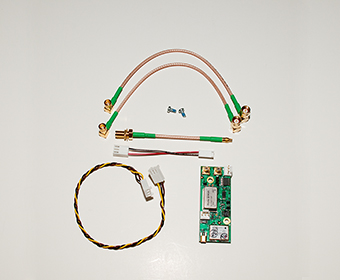
OpenBTS: N210 Instalasi GPSDO Kit
Kit Contents: 1 GPSDO module 1 Power cable (2 wires) 2 RS 232 cable, 22cm (3 wires) 1 RS 232 cable, 8cm (3 wires) 2 SMB right angle to SMA right angle cables 1 MMCX to SMA Bulkhead cable 2 Screws
Important: Please make all connections with the USRP powered OFF. GPSDO
Connectors: A. RS-232
(Pins: 1. TX, 2. GND, 3. RX)
B. 1 PPS C. 10 MHz Ref Clock D. Power (Pins: 1. GND, 2. GND, 3. +6V) E. GPS Antenna
Instructions: 1. Remove the daughterboard from the USRP motherboard if present. 2. USRP N2xx Only: Move J510 jumper on the motherboard from 1-2 to 2-3 in order to switch from external 10 MHz Ref Clock to GPSDO’s 10 MHz Ref Clock 3. Screw the GPSDO module in place with the screws provided. The screws are treated to avoid loosening with vibration. 4. Connect the GPSDO power cable to J509 (N200) / J101 (E1xx) on the motherboard, and then to connector D on the GPSDO module 5. Connect an SMB to SMA cable between connectors B and J506 (N200-PPS2) / J13 (E100–PPS) 6. Connect an SMB to SMA cable between connectors C and J507 (CLK REF2) / J10 (E100–REF IN) 7. The kit includes three non interchangeable serial cables to be used with di fferent USRP revisions and/or models . The 8cm long cable is for N200 series revision 4 or above and the E100 series revision 5 or above . The 22cm long cable with the black wire connected to the center pin on both ends of the cable is for the USRP N200 rev i sions 2 & 3 . The 22cm long cable with a colored dot on the connector that has ground (black wire) on pin 1 is for the USRP E100 revision 4. 8. USRP N2 xx Rev 2 & 3
Locate J312 on the front of the motherboard and connect either end of the appropriate 22cm lon g serial cable to it. If J312 on your USRP isn’t a keyed connector, please ensure to connect pin1 (TX) of connector A to the RX pin on J312. 9. USRP N2 xx Rev 4 or higher: Locate J 312 on the back of the motherboard near the GPSDO power connector and connect ei ther end of the 8cm long cable to it . Ettus Research LLC 1043 N Shoreline Blvd Suite 100 Mountain View, CA 94043 USA P
- +1
- 650 - 967 - 2870 – F
- +1
- 866 - 807 - 9801 – e ttus . com Rev. 1 . 9 – 10 October 201 2 10. USRP E1 xx Rev 4: Locate J86 next to the PPS SMA connector on the front of the motherboard. The serial cable connector that has the black wire (and a colored dot) on pin 1 has to be connected t o J86 ensuring that the black wire (pin 1) is connected to the GND pin of J86. 11. USRP E1xx Rev 5 or higher: Locate J86 on the back of the motherboard near the GPSDO power connector and connect either end of the 8cm long cable to it. 12. Connect the other end of the serial cable to con nector A on the GPSDO module . Ensure the black wire is connected to pin 2, if not it is either the wrong cable or connected backwards. 13. Remove the washer and nut from the MMCX to SMA - Bulkhead cable . Connect it to connector E and then insert SMA - Bulkhead co nnector through the hole in the rear panel . T ighten nut to fasten in place. 14. Replace the daughterboard pushing all the cables underneath. Module Specifications 1 PPS Accuracy ± 50ns to UTC RMS (1 - Sigma) GPS Locked Holdover Stability < ± 11 μ s over 3 hour period at +25C 1 PPS Output (OCXO Flywheel Generated) 3.3VDC CMOS RS - 232 Control NMEA & SCPI - 99 Control Commands, Integrated into UHD GPS Frequency L1, C/A 1574MHz GPS Antenna Active (3V compatible) or Passive GPS Receiver 50 Channels, Mobile, WAAS, EGNOS, MSAS capable Sensitivity Acquisition - 144dBm, Tracking - 160dBm TTFF Cold Start: <45 sec, Warm Start: 1 sec, Hot Start: 1 sec ADEV 1E - 11 at 1s Warm Up Time / Stabilization Time <5 min at +25C to 1E - 08 Accuracy Supply Voltage (Vdd) 6VDC Power Consumption <1.8W Max, 1.35W Typical Operating Temperature 0C to +60C Storage Temperature - 45C to 85C Oscillator Specifications Frequency Output 10MHz 10MHz Retrace ± 2E - 08 a fter 1 h our at 25C Frequency Stability Over Temperature (Unlock Condition) ± 2.5E - 08 Warm Up Time < 1 min at +25C Phase Noise at 10MHz 1Hz - 80dBc/Hz 10Hz - 110dBc/Hz 100Hz - 135dBc/Hz 1kHz - 145dBc/Hz 10kHz < - 145dBc/Hz Note: If your USRP model or revision is missing, please check online for an updated version of this document at : https://www.ettus.com/product/details/GPSDO
