Difference between revisions of "Antenna Pola Radiasi"
Onnowpurbo (talk | contribs) |
Onnowpurbo (talk | contribs) |
||
| Line 1: | Line 1: | ||
| − | + | Pola radiasi atau pola antena adalah representasi grafis dari sifat radiasi antena sebagai fungsi ruang. Artinya, pola antena menggambarkan bagaimana antena memancarkan energi elektromagnetik ke udara (atau bagaimana antena menerima energi). Penting untuk menyatakan bahwa antena memancarkan energi ke segala arah, setidaknya sampai batas tertentu, sehingga pola antena sebenarnya adalah tiga dimensi. Namun, umum untuk menggambarkan pola 3D ini dengan dua pola planar, yang disebut pola bidang utama. Pola bidang utama ini dapat diperoleh dengan membuat dua irisan melalui pola 3D melalui nilai maksimum pola atau dengan pengukuran langsung. Pola bidang utama inilah yang biasanya disebut sebagai pola antena. | |
| − | |||
| + | Pola radiasi antena adalah salah satu sifat dasarnya karena menunjukkan cara antena mendistribusikan energinya di udara. Ini umumnya terdiri dari sejumlah lobe (gelembung) dan jika diukur jauh dari antena itu tidak bergantung pada jarak. Ini adalah fungsi dari sudut dan dapat dinyatakan sebagai pola medan atau kekuatan. Biasanya dapat sepenuhnya ditentukan dari pola dalam dua bidang, tegak lurus satu sama lain, masing-masing bidang E dan H. Terkait dengan pola radiasi antena, terdapat beberapa parameter penting seperti daya pancar, efisiensi radiasi, directivity, gain, dan polarisasi antena. | ||
| − | + | Pola radiasi antena adalah representasi grafis dari elemen karakteristik radiasi antena. Pola antena biasanya merupakan representasi grafis dari karakteristik arah antena. Ini mewakili intensitas relatif dari radiasi energi atau jumlah kekuatan medan listrik atau magnet sebagai fungsi dari arah ke antena. Diagram antena diukur atau dihasilkan oleh program simulasi di komputer, misalnya, untuk menampilkan secara grafis keterarahan antena radar dan dengan demikian memperkirakan kinerjanya. | |
| − | |||
| − | |||
| − | |||
| − | |||
[[File:Horizontal1.png|center|300px|thumb]] | [[File:Horizontal1.png|center|300px|thumb]] | ||
| − | + | Berbeda dengan antena omni-directional, yang memancar secara seragam ke segala arah bidang, antena directional lebih memilih satu arah dan karena itu mencapai jangkauan yang lebih jauh dalam satu arah ini dengan daya transmisi yang lebih rendah. Pola radiasi antena secara grafis menggambarkan preferensi yang ditentukan oleh pengukuran. Karena resiprositas, yang menjamin karakteristik transmisi dan penerimaan antena yang sama, diagram menunjukkan daya transmisi yang didistribusikan secara terarah sebagai kekuatan medan dan sensitivitas antena selama penerimaan. | |
| − | [[File:Horizontal2.png|center|300px|thumb]] | + | [[File:Horizontal2.png|center|300px|thumb|Gambar: Penampang horizontal dari pola radiasi dalam sistem koordinat polar]] |
| − | + | ==Presentation Format== | |
| − | |||
Many display formats are used. Cartesian coordinate systems, as well as polar coordinate systems, are common. The main goal is to display a radiation diagram that is representative either horizontally (in azimuth) for a complete 360° representation or vertically (in elevation) mostly only for 90 or 180 degrees. In the Cartesian coordinate system, the data of an antenna can be represented better. Since these data can also be printed out as a table, the more descriptive representation as a locus curve in a polar coordinate system is usually preferred. In contrast to the Cartesian coordinate system, this indicates the direction directly. | Many display formats are used. Cartesian coordinate systems, as well as polar coordinate systems, are common. The main goal is to display a radiation diagram that is representative either horizontally (in azimuth) for a complete 360° representation or vertically (in elevation) mostly only for 90 or 180 degrees. In the Cartesian coordinate system, the data of an antenna can be represented better. Since these data can also be printed out as a table, the more descriptive representation as a locus curve in a polar coordinate system is usually preferred. In contrast to the Cartesian coordinate system, this indicates the direction directly. | ||
For easy handling, transparency and maximum versatility, radiation patterns are usually normalized to the outer edge of the coordinate system. This means that the measured maximum value is aligned to 0° and plotted on the upper edge of the diagram. Further measured values of the radiation diagram are usually displayed relative to this maximum value in dB (decibels). | For easy handling, transparency and maximum versatility, radiation patterns are usually normalized to the outer edge of the coordinate system. This means that the measured maximum value is aligned to 0° and plotted on the upper edge of the diagram. Further measured values of the radiation diagram are usually displayed relative to this maximum value in dB (decibels). | ||
| − | Usual Scales | + | ==Usual Scales== |
| + | |||
The scale in the diagram can be varied. Three types of plotting scales are in common usage; linear, linear logarithmic and modified logarithmic. The linear scale emphasizes the main radiation beam and usually suppresses all sidelobes, as they are often in the order of less than one-hundredth of the main lobes. However, the linear logarithmic scale represents the sidelobes well and is preferred when the level of all sidelobes is important. However, it leaves the impression that the antenna is bad because the main lobe is relatively small. The modified logarithmic scale (figure 4) emphasizes the shape of the major beam while compressing very low-level (<30 dB) sidelobes towards the center of the pattern. The main lobe is thus twice as large as the strongest side lobe, which is advantageous for visual presentations. However, this form of presentation is rarely used in technology because exact data would be difficult to read from it. | The scale in the diagram can be varied. Three types of plotting scales are in common usage; linear, linear logarithmic and modified logarithmic. The linear scale emphasizes the main radiation beam and usually suppresses all sidelobes, as they are often in the order of less than one-hundredth of the main lobes. However, the linear logarithmic scale represents the sidelobes well and is preferred when the level of all sidelobes is important. However, it leaves the impression that the antenna is bad because the main lobe is relatively small. The modified logarithmic scale (figure 4) emphasizes the shape of the major beam while compressing very low-level (<30 dB) sidelobes towards the center of the pattern. The main lobe is thus twice as large as the strongest side lobe, which is advantageous for visual presentations. However, this form of presentation is rarely used in technology because exact data would be difficult to read from it. | ||
| − | Horizontal Radiation Pattern | + | ==Horizontal Radiation Pattern== |
| + | |||
A horizontal antenna diagram is a plan view of the electromagnetic field of an antenna, represented as a two-dimensional plane with the antenna in the center. | A horizontal antenna diagram is a plan view of the electromagnetic field of an antenna, represented as a two-dimensional plane with the antenna in the center. | ||
| Line 32: | Line 29: | ||
With radar antennas, the ratio between main and sidelobes is important. This parameter directly influences the evaluation of the immunity of radar to interference. | With radar antennas, the ratio between main and sidelobes is important. This parameter directly influences the evaluation of the immunity of radar to interference. | ||
| − | Vertical Radiation Pattern | + | ==Vertical Radiation Pattern== |
| + | |||
The shape of the vertical pattern is a vertical cross cut of the three-dimensional graph. In the shown polar diagram (a quarter part of the circle) with the antenna site as the origin, the x-axis is the radar range, and the y-axis the aims height. One of the antenna measurement techniques is the Sun-Strobe-Recording using RASS-S, a measurement tool of Intersoft Electronics. The RASS-S (Radar Analysis Support System for Sites) is a radar manufacturer-independent system for evaluating the different elements of radar by connecting to signals which are already available and this under operational conditions. | The shape of the vertical pattern is a vertical cross cut of the three-dimensional graph. In the shown polar diagram (a quarter part of the circle) with the antenna site as the origin, the x-axis is the radar range, and the y-axis the aims height. One of the antenna measurement techniques is the Sun-Strobe-Recording using RASS-S, a measurement tool of Intersoft Electronics. The RASS-S (Radar Analysis Support System for Sites) is a radar manufacturer-independent system for evaluating the different elements of radar by connecting to signals which are already available and this under operational conditions. | ||
| Line 41: | Line 39: | ||
The radiant lines are marks of elevation angles, here in half-degree-steps. The unequal scales of the x-axis and the y-axis (many feet versus a lot of nautical miles) cause the non-linear spacing between the elevation angle marks. The height is shown as a linear grid pattern. A second (dotted) grid is orientated on the curvature of the earth. | The radiant lines are marks of elevation angles, here in half-degree-steps. The unequal scales of the x-axis and the y-axis (many feet versus a lot of nautical miles) cause the non-linear spacing between the elevation angle marks. The height is shown as a linear grid pattern. A second (dotted) grid is orientated on the curvature of the earth. | ||
| + | |||
| + | ==3D Antenna Patterns== | ||
[[File:Feedhorn.png|center|300px|thumb]] | [[File:Feedhorn.png|center|300px|thumb]] | ||
| − | + | ||
Three-dimensional antenna pattern of a feedhorn, | Three-dimensional antenna pattern of a feedhorn, | ||
| − | + | ||
Figure 4: Three-dimensional antenna pattern of a feed horn | Figure 4: Three-dimensional antenna pattern of a feed horn | ||
Revision as of 13:14, 16 November 2022
Pola radiasi atau pola antena adalah representasi grafis dari sifat radiasi antena sebagai fungsi ruang. Artinya, pola antena menggambarkan bagaimana antena memancarkan energi elektromagnetik ke udara (atau bagaimana antena menerima energi). Penting untuk menyatakan bahwa antena memancarkan energi ke segala arah, setidaknya sampai batas tertentu, sehingga pola antena sebenarnya adalah tiga dimensi. Namun, umum untuk menggambarkan pola 3D ini dengan dua pola planar, yang disebut pola bidang utama. Pola bidang utama ini dapat diperoleh dengan membuat dua irisan melalui pola 3D melalui nilai maksimum pola atau dengan pengukuran langsung. Pola bidang utama inilah yang biasanya disebut sebagai pola antena.
Pola radiasi antena adalah salah satu sifat dasarnya karena menunjukkan cara antena mendistribusikan energinya di udara. Ini umumnya terdiri dari sejumlah lobe (gelembung) dan jika diukur jauh dari antena itu tidak bergantung pada jarak. Ini adalah fungsi dari sudut dan dapat dinyatakan sebagai pola medan atau kekuatan. Biasanya dapat sepenuhnya ditentukan dari pola dalam dua bidang, tegak lurus satu sama lain, masing-masing bidang E dan H. Terkait dengan pola radiasi antena, terdapat beberapa parameter penting seperti daya pancar, efisiensi radiasi, directivity, gain, dan polarisasi antena.
Pola radiasi antena adalah representasi grafis dari elemen karakteristik radiasi antena. Pola antena biasanya merupakan representasi grafis dari karakteristik arah antena. Ini mewakili intensitas relatif dari radiasi energi atau jumlah kekuatan medan listrik atau magnet sebagai fungsi dari arah ke antena. Diagram antena diukur atau dihasilkan oleh program simulasi di komputer, misalnya, untuk menampilkan secara grafis keterarahan antena radar dan dengan demikian memperkirakan kinerjanya.
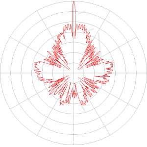
Berbeda dengan antena omni-directional, yang memancar secara seragam ke segala arah bidang, antena directional lebih memilih satu arah dan karena itu mencapai jangkauan yang lebih jauh dalam satu arah ini dengan daya transmisi yang lebih rendah. Pola radiasi antena secara grafis menggambarkan preferensi yang ditentukan oleh pengukuran. Karena resiprositas, yang menjamin karakteristik transmisi dan penerimaan antena yang sama, diagram menunjukkan daya transmisi yang didistribusikan secara terarah sebagai kekuatan medan dan sensitivitas antena selama penerimaan.
Presentation Format
Many display formats are used. Cartesian coordinate systems, as well as polar coordinate systems, are common. The main goal is to display a radiation diagram that is representative either horizontally (in azimuth) for a complete 360° representation or vertically (in elevation) mostly only for 90 or 180 degrees. In the Cartesian coordinate system, the data of an antenna can be represented better. Since these data can also be printed out as a table, the more descriptive representation as a locus curve in a polar coordinate system is usually preferred. In contrast to the Cartesian coordinate system, this indicates the direction directly.
For easy handling, transparency and maximum versatility, radiation patterns are usually normalized to the outer edge of the coordinate system. This means that the measured maximum value is aligned to 0° and plotted on the upper edge of the diagram. Further measured values of the radiation diagram are usually displayed relative to this maximum value in dB (decibels).
Usual Scales
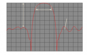
The scale in the diagram can be varied. Three types of plotting scales are in common usage; linear, linear logarithmic and modified logarithmic. The linear scale emphasizes the main radiation beam and usually suppresses all sidelobes, as they are often in the order of less than one-hundredth of the main lobes. However, the linear logarithmic scale represents the sidelobes well and is preferred when the level of all sidelobes is important. However, it leaves the impression that the antenna is bad because the main lobe is relatively small. The modified logarithmic scale (figure 4) emphasizes the shape of the major beam while compressing very low-level (<30 dB) sidelobes towards the center of the pattern. The main lobe is thus twice as large as the strongest side lobe, which is advantageous for visual presentations. However, this form of presentation is rarely used in technology because exact data would be difficult to read from it.
Horizontal Radiation Pattern
A horizontal antenna diagram is a plan view of the electromagnetic field of an antenna, represented as a two-dimensional plane with the antenna in the center.
The interest in this representation lies in the simple acquisition of the directivity of the antenna. Usually, the value -3 dB is also given on the scale as a dotted circle. The crossing points between the main lobe and this circle result in the so-called half power beam width of the antenna. Other easily readable parameters are the forward/backward ratio, i.e. the ratio between the main lobe and the back lobes, as well as the size and direction of the sidelobes.
With radar antennas, the ratio between main and sidelobes is important. This parameter directly influences the evaluation of the immunity of radar to interference.
Vertical Radiation Pattern
The shape of the vertical pattern is a vertical cross cut of the three-dimensional graph. In the shown polar diagram (a quarter part of the circle) with the antenna site as the origin, the x-axis is the radar range, and the y-axis the aims height. One of the antenna measurement techniques is the Sun-Strobe-Recording using RASS-S, a measurement tool of Intersoft Electronics. The RASS-S (Radar Analysis Support System for Sites) is a radar manufacturer-independent system for evaluating the different elements of radar by connecting to signals which are already available and this under operational conditions.
Figure 3: Vertical antenna pattern with cosecant squared characteristic
In the shown Figure 3, the measurement units are nautical miles as range, and feet as height. Both measurement units are still used in Air- Traffic- Management by historical reasons. These units are of secondarily meaning only because the plotted quantity of radiation pattern is defined as a relative level. This means the boresight axis has got the value of the (theoretical) maximum range calculated with the help of the Radar Equation. The shape of the plot provides the required information only! To get absolute values you need a second plot, measured under the same conditions. These two plots you can compare and then you achieve over increasing or decreasing the antennas performance.
The radiant lines are marks of elevation angles, here in half-degree-steps. The unequal scales of the x-axis and the y-axis (many feet versus a lot of nautical miles) cause the non-linear spacing between the elevation angle marks. The height is shown as a linear grid pattern. A second (dotted) grid is orientated on the curvature of the earth.
3D Antenna Patterns
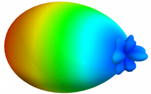
Three-dimensional antenna pattern of a feedhorn,
Figure 4: Three-dimensional antenna pattern of a feed horn
Antenna diagrams in three-dimensional representation are mostly computer-generated images. Mostly they are generated by simulation programs whose values are astonishingly close to a real measured diagram. To generate a real measured diagram means an immense measuring effort since each pixel of the image represents its own measured value.
Most antenna measurement programs, therefore, choose a compromise for this representation. Only a vertical and a horizontal section through the antenna diagram are available as real measured values. All other pixels are calculated by multiplying the entire measurement curve of the vertical diagram by a single measurement value of the horizontal diagram. The computing power required is enormous. With the exception of a pleasing representation in presentations, the benefit is doubtful, since no new information can be gained from this representation compared to the two individual diagrams (horizontal and vertical antenna diagram). On the contrary: especially in the peripheral zones, a diagram generated with this compromise should deviate considerably from the reality.
Also, 3D diagrams can be represented in Cartesian as well as in polar coordinates.


